DC House Power Distribution Network

The DC Project is an alternate solution for rural electrification that has been going on for 10 years. This project is testing the feasibility of incorporating a network connecting DC houses to share power.

OUR TEAM

Deepthi Ravuru

EE undergrad

Researched, designed, and tested the DC Distribution Network using Simulink. 

Jonathan Ogden

EE Undergrad

Researched, designed, and tested the DC Distribution Network using Simulink. 

Acknowledgements

Our team would like to thank our advisor, Dr. Taufik, for supporting and guiding us through the project. We would also like to thank the Cal Poly EE department and the Electric Power Research Institute for making this project possible.

OUR PROJECT'S DIGITAL POSTER

Abstract

Since 2010 the California Polytechnic State University, San Luis Obispo has had an ongoing project to develop DC to DC power systems technology. These projects have the potential to bring power to people in remote rural communities using renewable sources and batteries. These systems are preferable to the traditional AC to DC system due to low power loss form the conversion process. 

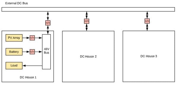
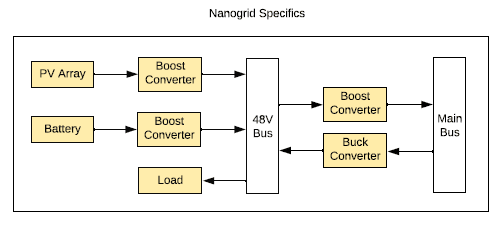
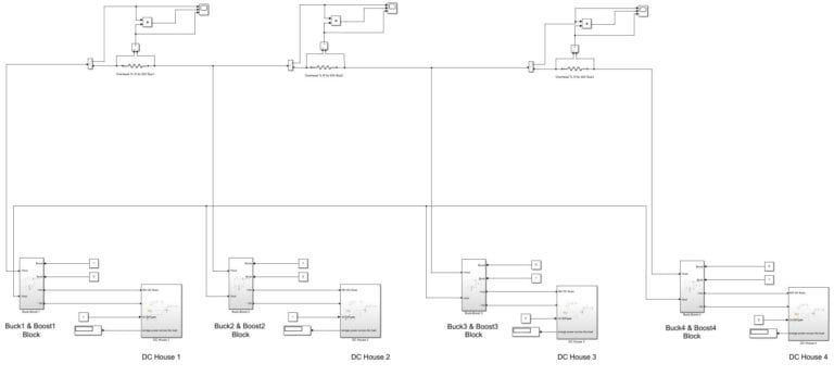
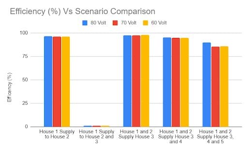
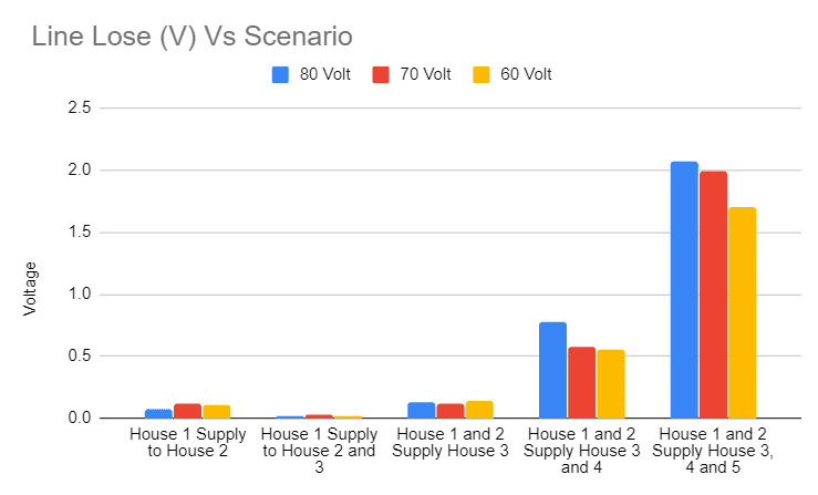
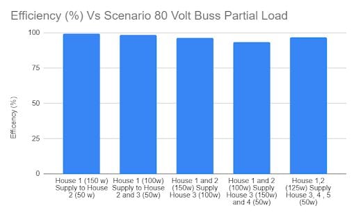
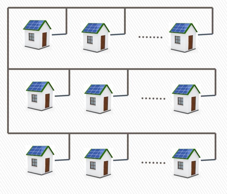
An area of interest to this project is small communities of rural homes clustered together. For this experiment, a preliminary MATLAB Simulink model was created to test the viability of such a cluster of DC houses connected by an external bus that allows the houses to share power. Tests will be performed to determine if this network is feasible.

Design Specifications

  • The maximum power supplied by the PV array is 330W
  • Each DC house has a maximum power load of 200W and has a battery to store energy.
  • The boost and buck converters were designed from scratch with a control system.
  •  The local bus voltage of the DC house is 48V and the external DC Bus is at a higher voltage.

Design

  • The PV array and the battery are connected to a boost converter to yield a 48V local bus voltage.
  • The power is supplied to the house through the local bus.
  • The 48V from the local bus is boosted to a higher voltage for the external bus if the house is supplying power.
  • The external bus voltage is stepped down to 48V local bus voltage through the buck converter when then house is absorbing power from its neighbor.
  • Five houses were connected to the external bus to be tested under various scenarios.
This project was sponsored by the Electric Power Research Institute

Simulink Model

  • The figure above shows the DC house distribution network in Simulink, note that there are only four houses due to image resolution issues, but 5 houses were connected to the external bus.
  • The resistors in the grid represent the resistance of overhead lines when the houses are 75ft apart.
  • The boost and buck converters are manually turned on and off using switches.

Testing

  • Test 1: the external bus was tested at 3 different voltages, 60V, 70V, and 80V, to determine the most efficient bus voltage.
    • The houses were at full load, where the battery of the suppling house(s) was turned on.
    • These tests were conducted for 5 different scenarios:
      • House 1 supply to House 2 
      • House 1 supply to House 2 and 3
      • House 1 and 2 supply House 3 
      • House 1 and 2 supply House 3 and 4
      • House 1 and 2 supply House 3, 4, and 5
  • Test 2: At the most efficient external bus voltage, tests were conducted for varying load:
    • House 1 (150 w) Supply to House 2 (50 w)
    • House 1 (100w) Supply to House 2 and 3 (50w)
    • House 1 and 2 (150w) Supply House 3 (100w)
    • House 1 and 2 (100w) Supply House 3 (150w) and 4 (50w)
    • House 1,2  (125w) Supply House 3, 4 , 5 (50w)

Test 1 Data

  • In scenario 2, there was more demand for power than what can be supplied by the PV array, so the PV crashed.
  • We concluded that the network is most efficient at 80V, with an average efficiency of  94% without scenario 2. 
  • According to the chart above, the higher the bus voltage, the higher the line losses.
    • We suspect that this was caused due to the lack of constant power output from the boost and buck converters.

Test 2 Data

  • The more the loads vary, the efficiency of the network is lowered.
  • At varying loads, the network’s average efficiency was around 96%. 

Conclusion

  • The results of this project displayed that this network is feasible.
  • In the future, the network will be tested for various scenarios and under non-ideal conditions.
  • A filter will also be added to the boost and buck converter block to prevent the current from switching.

Share

Share on facebook
Share on twitter
Share on linkedin

Coronavirus Update and Resources