Free Vibration of an Airplane Wing under Coupled Bending and Torsion: Approximation of the natural frequencies using uncoupled mode shapes for torsion and bending

Wing deflecting under coupled torsion and bending
The scope of our research involved looking at an airplane wing that is undergoing coupled torsion and bending in free vibration. The goal to was to model the wing as a cantilever beam and use the uncoupled mode shapes to approximate the natural frequencies of a beam with coupled properties.

Our Team

Portrait of Kellen Andrew

Kellen Andrew

Student Researcher

Hi! My name’s Kellen and I am a third year Aerospace Engineering with a concentration in Astronautics. When I’m not in class, I’m either riding bikes, repairing bikes, or building up an entirely new frame in the Hangar. 

Matthew Schoenau

Student Researcher

Hi! My name is Matthew and I am a 4th year Aerospace Engineering Major with a concentration inn Aeronautics. I enjoy flying, diving and backpacking, but my wallet doesn’t. 

Acknowledgements

We would like to thank Dr. Deffo for his consistent support throughout the project and his dedication to helping us become more capable engineers. 

Digital Poster

INTRODUCTION/ MOTIVATION

  • Modeling an aircraft wing as a cantilevered beam can be a useful tool in conducting structural analysis. [1]
  • As the lift distribution on aircraft wings is not uniform, the wings usually undergo both bending and torsional forces.
  • The angular displacement and traverse deflection are coupled for composite beams.
  • In this project we studied the free vibration of such beams. Finding the natural frequency as an exact solution is very challenging so we used the Rayleigh-Ritz Method instead. [1]
  • With the natural frequencies known, one can then optimize a damper for the wing/fuselage system.

SIGNIFICANT EXPRESSIONS

Coupled Equations of Motion

$$\left.\overline{\rho I_{p}} \frac{\partial^{2} \theta}{\partial t^{2}}+m d \frac{\partial^{2} v}{\partial t^{2}}+\frac{\partial}{\partial x}\left(\overline{G J} \frac{\partial \theta}{\partial x}-K \frac{\partial^{2} v}{\partial x^{2}}\right)\right)=r(x, t)$$

$$\left.m\left(\frac{\partial^{2} v}{\partial t^{2}}+d \frac{\partial^{2} \theta}{\partial t^{2}}\right)+\frac{\partial^{2}}{\partial x^{2}}\left(\overline{E I} \frac{\partial^{2} v}{\partial t^{2}}-K \frac{\partial \theta}{\partial x}\right)\right)=f(x, t)$$

Assumed Mode Shapes

Bending:

$$\psi_j=\cosh (\gamma_j x)-\cos (\gamma_j x)-\beta_j(\sinh (\gamma_j x)-\sin (\gamma_j x))$$

where,

$$\beta_j=\frac{\cosh (\gamma_j l)+\cos (\gamma_j l)}{\sinh (\gamma_j l)+\sin (\gamma_j l)}$$

Torsion:

$$\phi_i=\sin (\alpha_i x)$$

where,

$$\alpha_i=\frac{(2 i-1)\pi}{2}$$

Coupled Strain Energy

$$\boldsymbol{U}=\frac{1}{2}\int_{0}^{l}\left[\begin{array}{l}\frac{\partial \theta}{\partial x} \\\frac{\partial^{2} v}{\partial x^{2}}\end{array}\right]^{T}\left[\begin{array}{ll}\overline{G J} & -K \\-K & \overline{E I}\end{array}\right]\left[\begin{array}{l}\frac{\partial \theta}{\partial x} \\\frac{\partial^{2} v}{\partial x^{2}}\end{array}\right] dx$$

Coupled Kinetic Energy

$$K =\frac{1}{2}\int_{0}^{l}\left[m\left(\frac{\partial v}{\partial t}\right)^{2}+2 m d \frac{\partial \theta}{\partial t} \frac{\partial v}{\partial t}+\overline{\rho I_{p}}\left(\frac{\partial \theta}{\partial t}\right)^{2}\right] d x$$

Lagrange's Equation[2]

$$\frac{\partial}{\partial t}\left(\frac{\partial K}{\partial \dot{q}_{i}}\right)+\frac{\partial U}{\partial q_{i}}=0$$

Cal Poly mark

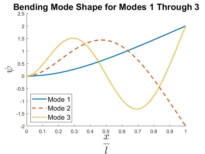
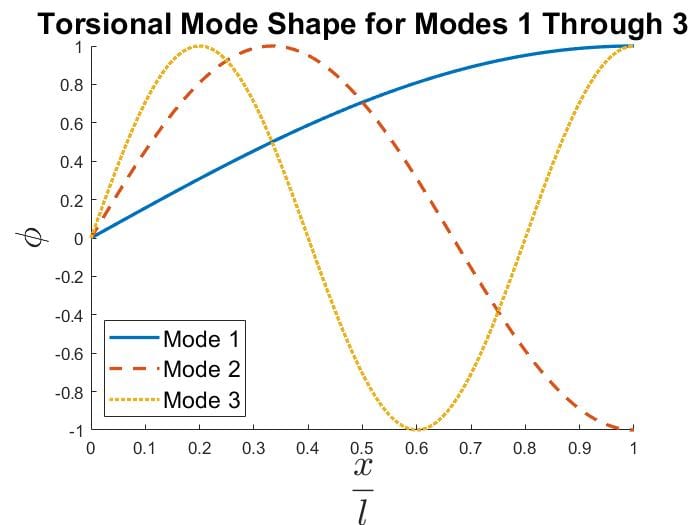
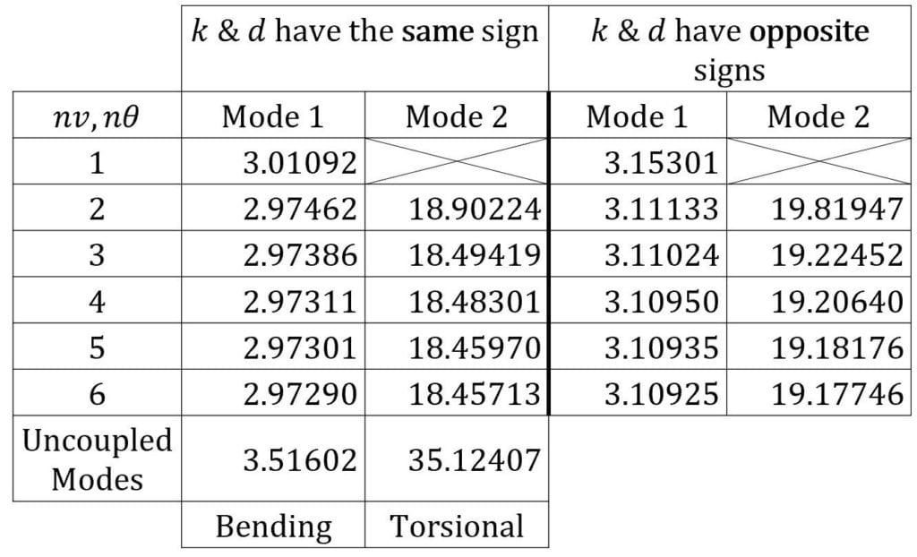
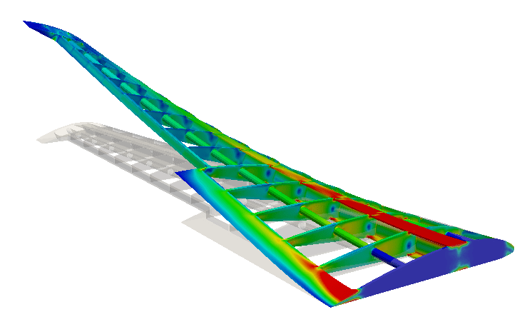
Free Vibration of a Wing under Coupled Bending and Torsion

Kellen Andrew & Matthew Schoenau
Dr. Deffo, Aerospace Engineering

UNCOUPLED MODE SHAPES

Bending Mode Shapes
Torsional Mode Shapes

References: 
[1] Dewey H. Hodges, G. Alvin Pierce, Introduction to structural Dynamics and Aeroelasticity, second edition, Cambridge University Pres, 2011 
[2] Professor J. Kim Vandiver, An Introduction to Lagrange Equations, MIT OpenCourse Ware Fall 2011

PROCEDURE

Rayleigh Ritz Method

Relies on solving Lagrange’s Equation using “admissible functions” (fi  , gj) that satisfy the following conditions:

  1. fi  , gj must satisfy the boundary conditions of the beam.
  2. fi  , gj must be differentiable enough to compute Lagrange’s Equation without issue.
  3.  fi  , gj must each form a complete set of functions.
  4. fi  andfj  (i≠j) must be linearly independent & gi and gj (i≠j) must be linearly independent 
  • Uncoupled bending/torsion modes as assumed mode shapes
  • Lagrange’s Equation to obtain homogeneous system of equations
  • Determinevalues of ω (oscillation frequency) for nontrivial solutions to the system.
  • Implementation in terms of the dimensionless parameter, $\omega^2=\frac{\lambda^2 E I}{m L^4}$

RESULTS

  • Rayleigh Ritz Method can be altered to achieve approximations for higher modes as well as different levels of accuracy.
  • To find nth mode natural frequency, use assumed mode shapes i = 1,2,…,n in approximation
  • Approximation converges to the actual value as more assumed mode shapes are used i > n.
  • Approximation is monotonic decreasing, i.e., higher number of modes provide better approximate of lower frequencies.

Table of Natural Frequency Coefficients †

Table of Natural Frequencies

† Natural Frequency is obtained by the following: 

$$\omega=Coefficient\cdot\sqrt{\frac{E I}{m L^4 }}$$

DISCUSSION

  • Notice that the apparent limit of the approximation depends on whether k and d have the same or opposite signs
  • Opposite signs result in slightly higher frequencies for Modes 1,2
  • Additionally, the coupled behavior significantly alters the natural frequencies from the uncoupled cases
  • With the results above, one could now design a damper system to deaden vibrations near these frequencies and ultimately avoid the potentially catastrophic phenomenon that is resonance.

Share

Share on facebook
Share on twitter
Share on linkedin

Coronavirus Update and Resources