Effects of Defects on Mechanical Strength in Fused Deposition Modeling
Materials Engineering | Fall 2021
In recent history, Fused Deposition Modeling (FDM) has become a popular method for producing parts due to its simplicity and cost effectiveness. However, common defects have led to unexpected results as misprints can affect the strength of the printed samples. This study explored the effects of defects by tensile testing samples with different defects and comparing strengths relative to one another. Nondefective samples, samples with layer shifts at the gauge length, samples with a seam down the center of the gauge length, and samples with periodic bumps were all tested to gather data to compare the strengths of the of the parts. As expected, all of the defects lowered the strengths of the parts, however, some parts became much weaker than others.
Our Team
Daniel Xu
Daniel Xu is a Mechanical Engineering major concentrating in Mechatronics. He aspires to one day help develop rovers and satellites to help unravel the mysteries of the universe.
Kevin Ibrahim
Kevin Ibrahim is a Materials Engineering major. He aspires to work in the biomedical industry researching, developing, and testing new materials.
Acknowledgements
Thank you to Lockheed Martin for sponsoring this research project. Additionally, we thank Dr. Kivy and Dr. Wang for guidance as well as the College of Engineering at Cal Poly for the support necessary for this project.
Effects of Defects on Mechanical Strength in Fused Deposition Modeling
Background
FDM, or Fused Deposition Modeling, is used to produce 3D printed parts
Common defects like layer shifts, bumps, and seams create locations of potential failure
Samples printed with deliberate defects were produce to mimic the defects seen in industry
The coupons, modeled after ASTM D638 Type IV, were tensile tested to measure the strength of the designs
Results were tabulated and displayed graphically to compare differences between each design
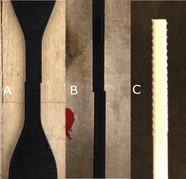
Figure 1: Some common defects that were replicated, including (A) X-Layer Shift, (B) Y-Layer Shift, and (C) periodic bumps. (D) FDM 3D Printer
Objective
To find the effects that multiple unique defects have on the mechanical strength of FDM 3D printed samples.
Procedure
The samples were designed using SolidWorks following dimensions from D638.
The coupon STL files were converted to gcode using Cura and then printed on two Creality Ender 3 v2’s in the ZXY orientation.
6 types of samples were designed to be tensile tested.
Samples were tensile tested using a Shimadzu Universal Testing Machine at a strain rate of 5 mm/min, or 0.2 in/min until broken.
At least 3 and up to 8 samples were tested of each design to produce robust data.
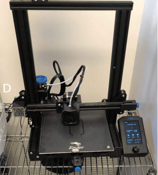
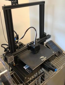
Figure 2: Creality Ender 3 v2 Printer that was used to print the coupons
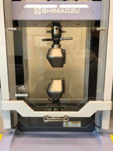
Figure 3: Shimadzu Universal Testing Machine that was used for the tensile tests
Results
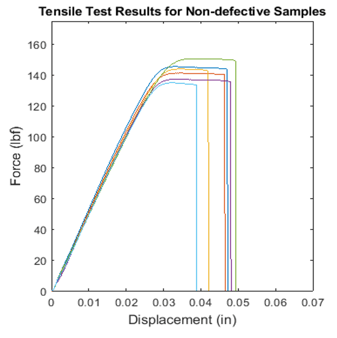
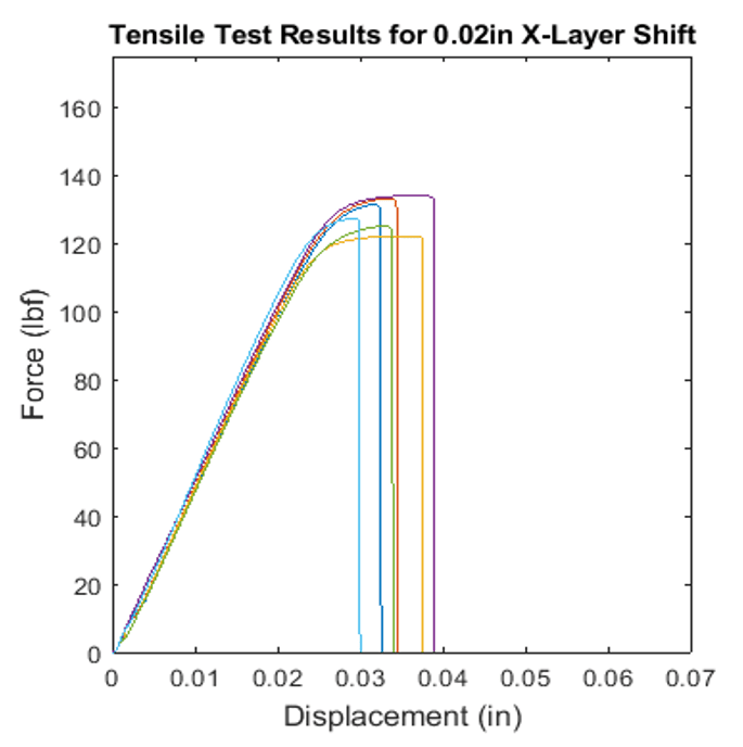
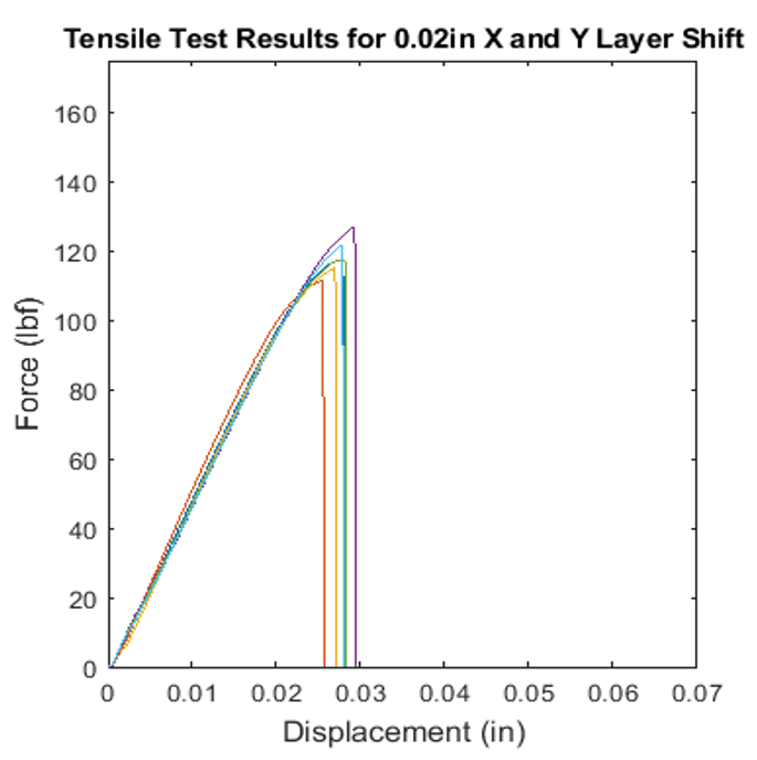
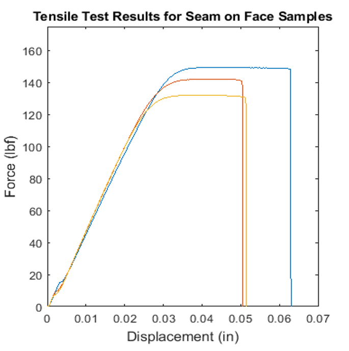
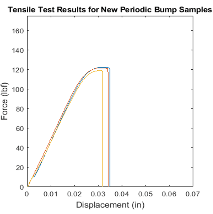
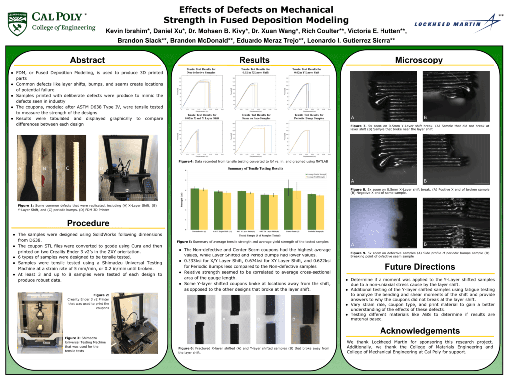
Figure 4: Data recorded from tensile testing converted to lbf vs. in. and graphed using MATLAB
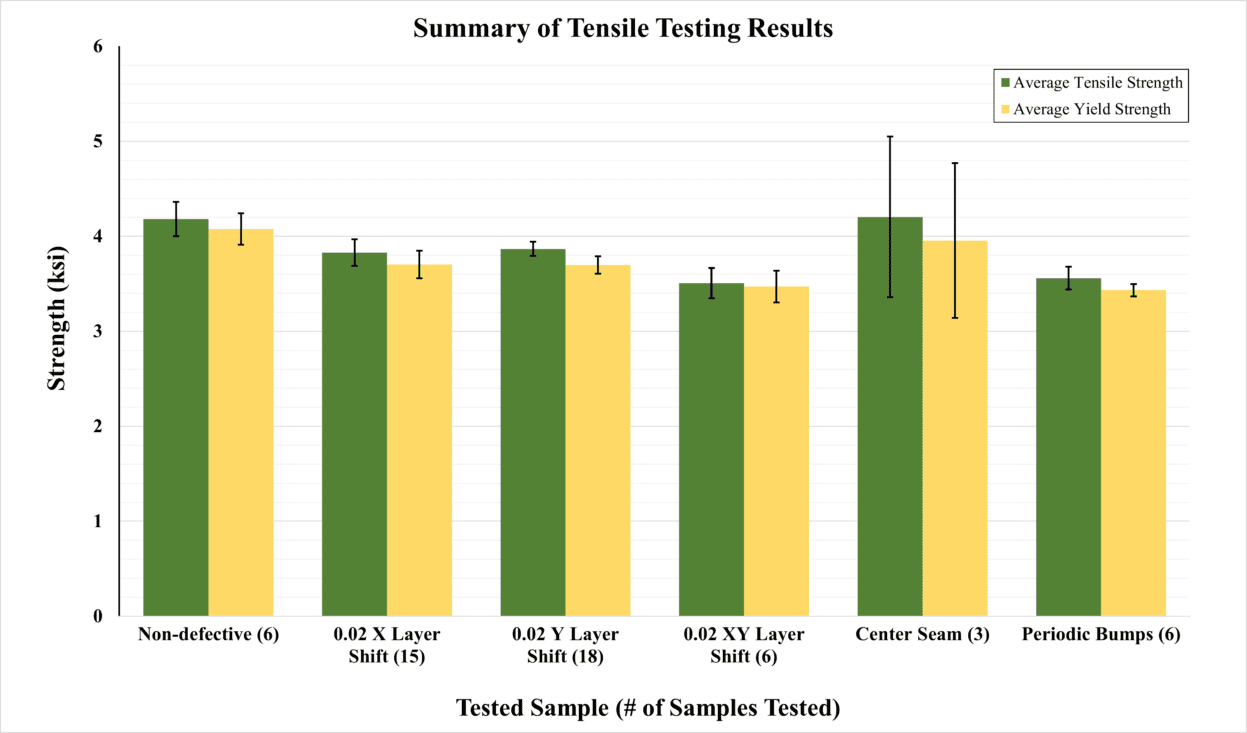
Figure 5: Summary of average tensile strength and average yield strength of the tested samples
The Non-defective and Center Seam coupons had the highest average values, while Layer Shifted and Period Bumps had lower values.
0.333ksi for X/Y Layer Shift, 0.674ksi for XY Layer Shift, and 0.622ksi for Periodic Bumps less compared to the Non-defective samples.
Relative strength seemed to be correlated to average cross-sectional area of the gauge length.
Some Y-layer shifted coupons broke at locations away from the shift, as opposed to the other designs that broke at the layer shift.
Results
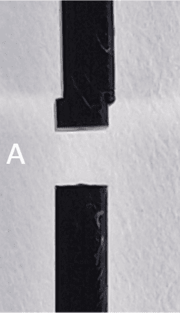
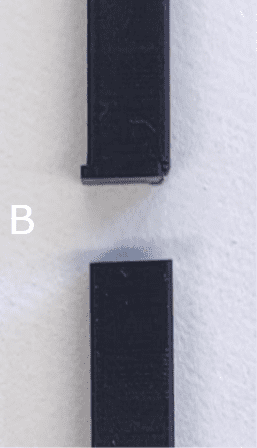
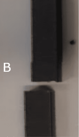
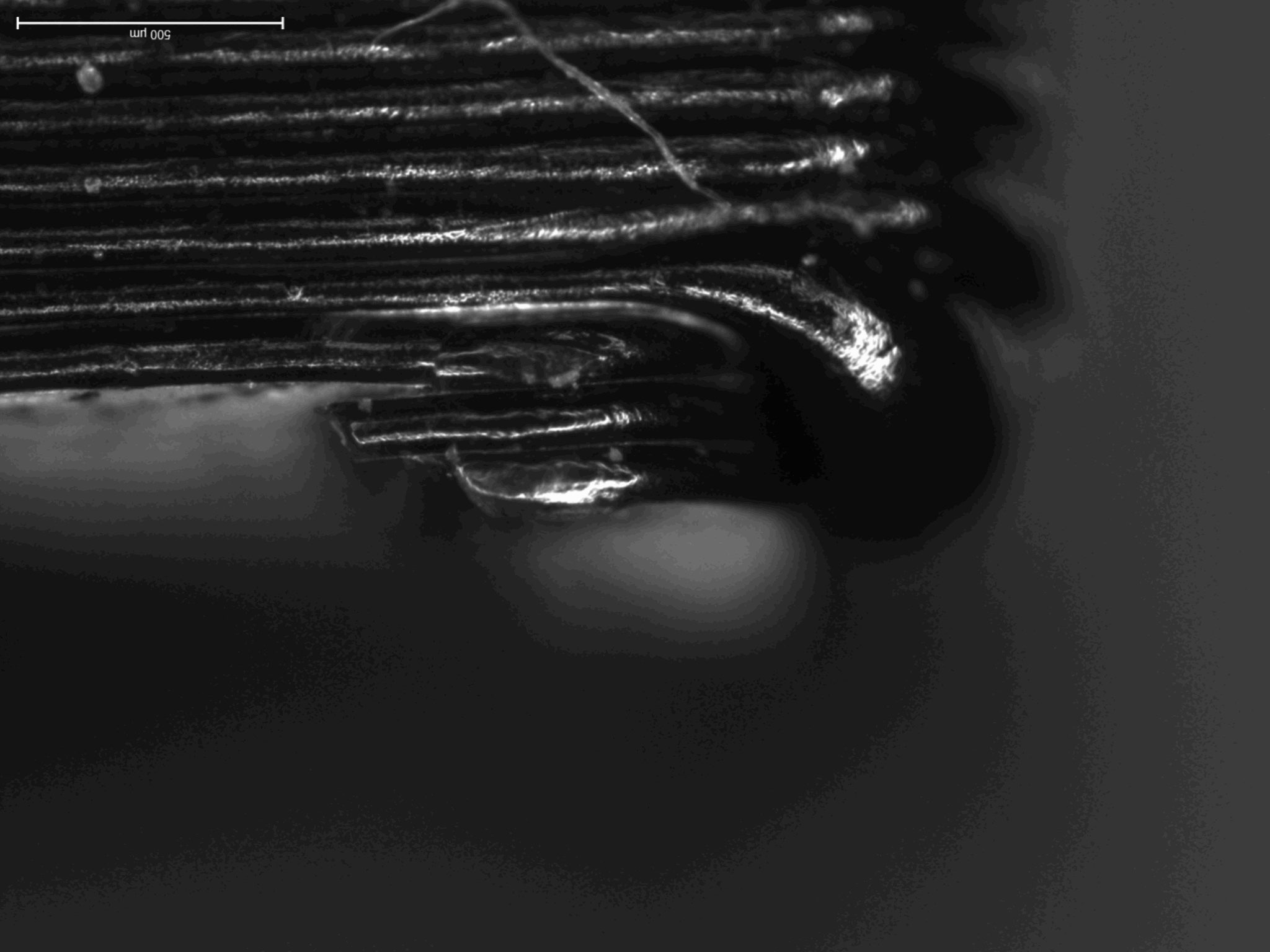
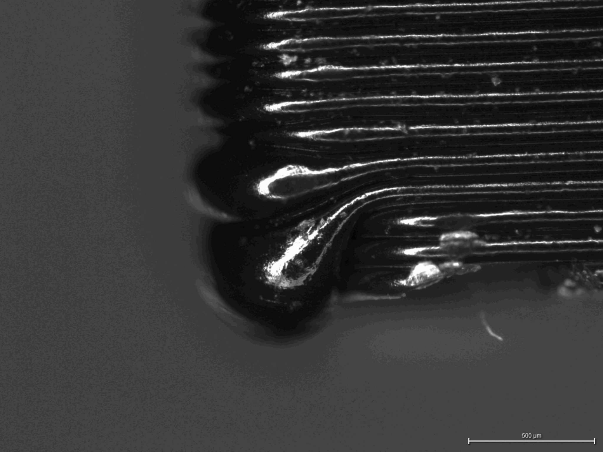
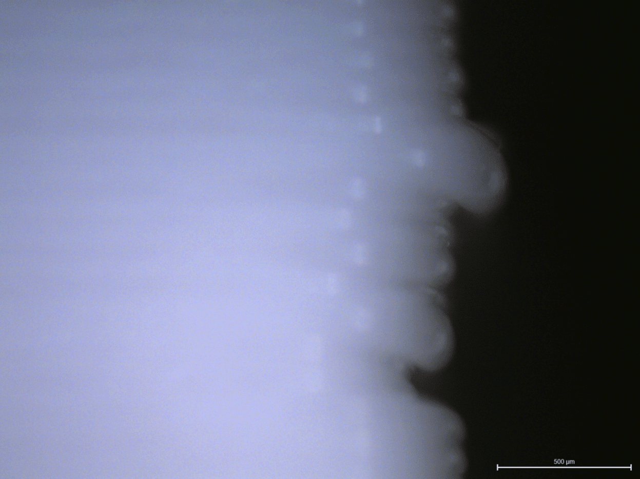
Figure 6: Fractured X-layer shifted (A) and Y-layer shifted samples (B) that broke away from the layer shift.
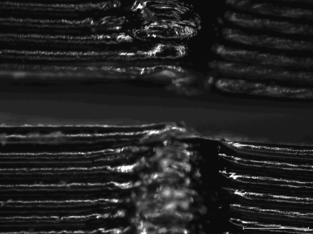
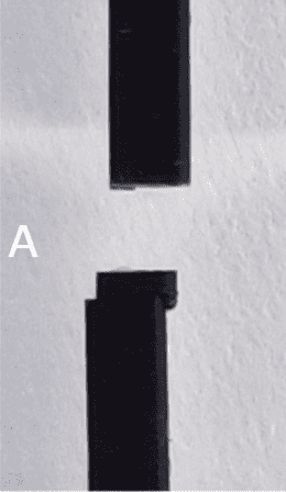
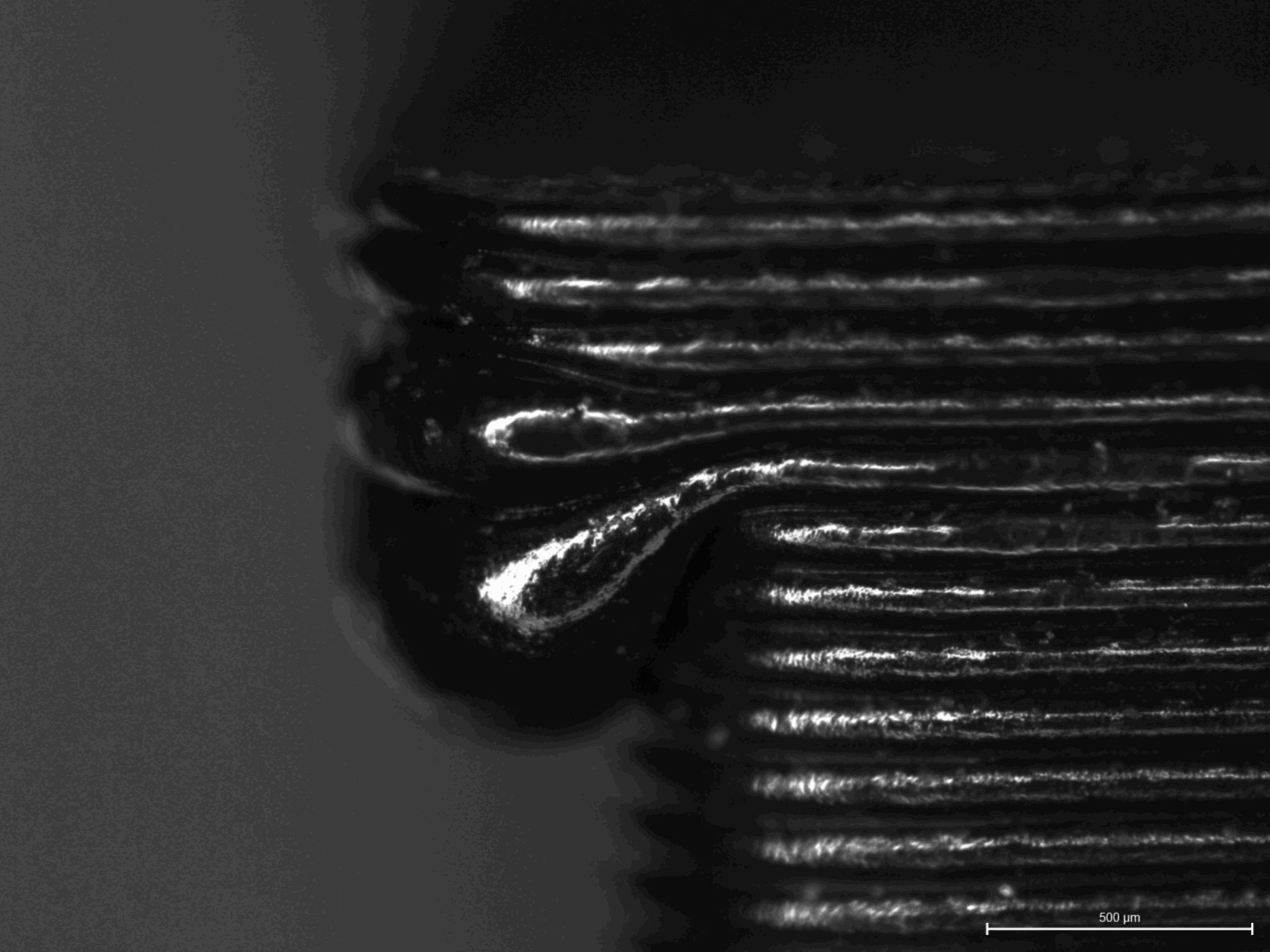
Figure 9. 5x zoom on defective samples (A) Side profile of periodic bumps sample (B) Breaking point of defective seam sample
Future
Determine if a moment was applied to the Y-Layer shifted samples due to a non-uniaxial stress cause by the layer shift.
Additional testing of the Y-layer shifted samples using fatigue testing to analyze the bending and shear moments of the shift and provide answers to why the coupons did not break at the layer shift.
Vary strain rate, coupon type, and print material to gain a better understanding of the effects of these defects.
Testing different materials like ABS to determine if results are material based.

")


")